Using DS1307 Real-time clock is discussed. A module in AliExpress costs only about $1. It even consists of a 32k EEPROM called AT24C32.
Showing posts with label Circuit. Show all posts
Wednesday, May 18, 2016
Thursday, April 21, 2016
Wednesday, November 25, 2015
CC2531 Zigbee USB Dongle
In this article, we discuss about using CC2531 USB Evaluation Module Kit for wireless communication. At first, a zip file - CC USB Firmware Library and Examples, was downloaded from TI's website. After that, USB RF Modem Example in CC USB Software Examples User’s Guide was tested.
Labels:
2.4 GHz,
8051,
C,
C++,
CC2530,
Circuit,
Communication,
Electronics,
firmware,
Free Software,
Hardware,
IAR,
IEEE 802.15.4,
Microcontroller,
Robotics,
TI,
USB,
Wireless,
Zigbee
Tuesday, November 24, 2015
Wireless Communication using CC2530 Zigbee Wireless MCU
CC2530 is an system-on-chip (SoC) solution for IEEE 802.15.4 and Zigbee that combines RF transceiver and 8051 MCU. To develop a wireless module using it, we had bought a CC2530DK devolopment kit that consists of 2 CC2530EM Evaluation Modules, 2 SmartRF05EB Evaluation Boards, and a CC2531 USB Dongle. It cost about USD 400. At first, we installed SmartRF Studio which was available for free at TI's website.
Labels:
2.4 GHz,
8051,
C,
C++,
CC2530,
Circuit,
Communication,
Electronics,
firmware,
Free Software,
Hardware,
IAR,
IEEE 802.15.4,
Microcontroller,
Robotics,
TI,
Wireless,
Zigbee
Saturday, September 19, 2015
Controlling Your Hardware from the Web Using Arduino
Using Arduino Ethernet shield 2 to control a hardware from the web is discussed.
Arduino Ethernet 2 Library is used to implement in an Arduino Uno board as a server in an example as well as a client in an another example.
The latest version Arduino IDE ( 1.7.6 in our case ) is used in the following examples. An Arduino Uno board with Ethernet shield 2 is shown below.
Labels:
Arduino,
Circuit,
Code,
Electronics,
Embedded System,
Ethernet,
firmware,
Interface,
internet,
MCU,
Mechatronics,
Microcontroller,
Robotics,
Sensor,
Signal Processing,
Web
Thursday, September 10, 2015
Accelerometer LIS3DSH
LIS3DSH is an 3-axis MEMS accelerometer made by STMicroelectronics. Its full scale range is selectable from ±2g to ±16g. The size is small and it is only 3mm x 3mm. Either SPI or I2C can be used to interface with it. Supply voltage is from 1.71 V to 3.6 V. In this article, testing and evaluation of STEVAL-MKI134V1 adapter board is discussed.
Labels:
8051,
Accelerometer,
Arduino,
ARM,
AT89C51CC03,
Circuit,
Code,
Electronics,
Embedded System,
firmware,
I2C,
Interface,
LPC54102,
MCU,
Mechatronics,
Microcontroller,
Robotics,
Sensor,
Signal Processing,
SPI
Wednesday, September 3, 2014
Thursday, March 6, 2014
Reading Rotary Encoder Using Microcontroller
Rotary encoders are commonly used for measuring angular position or motion sensing.
An optical encoder has a disc with a pattern of cutouts. As the disc rotated, an LED light that shines on photo detector is turned on and off accordingly to produce a digital waveform.
Gray code is normally used in encoders instead of ordinary binary code to prevent glitches. In Gray code, the number of changing bits between successive numbers is only 1. The following table shows 2 bit Gray code from 0 to 3.
Monday, July 8, 2013
CAN bus
CAN bus (controller area network) is a vehicle bus standard designed to allow microcontrollers and devices to communicate with each other. CAN bus is a message-based protocol, designed specifically for automotive applications but now also used in other areas such as aerospace, industrial automation and medical equipment.
The advantages of CAN bus compared to RS232 communication are as follows.
Friday, June 28, 2013
Using Analog to Digital Converter of AT89C51CC01 Microcontroller
Using AT89STK-06 starter kit, I have written a few C code to read an analog to digital converter (ADC) input of AT89C51CC01 which is an 8051 microcontroller. It has 8 multiplexed ADC inputs with 10 bit resolution. As an example, ADC input pin 7 which is connected to a variable resister is read.
Thursday, February 28, 2013
Non-inverting Amplifier Using op-amp
When PiezoDrive PDX 150 amplifier that I used to drive a piezoelectric actuator was damaged, I need to find a way to use an existing spare amplifier. The spare amplifier shown in the following figure has input voltage -2 V to 12 V and output voltage -20 V to 120 V. Its gain is only 10 while the damaged one is 20. Therefore, I decided to design and use an additional preamplifier with gain 2.
The input to that amplifier is -1 V to 6 V and its output shold be -2 V to 12 V. Since I need non-inverted output, I have used an op-amp with non-inverting configuration. I have also used a trimmer so that it is possible to fine tune the gain. Readily available LM358N op-amp IC is arbitrarily picked up. The schematic circuit diagram and resulting amplifier using available components in our lab is shown below. Since the non-inverting amplifier has very high input impedance, I have used additional 56k resister to prevent it from floating.
When tuning the amplifier to get exact gain of 2, it looked unreliable to use peak to peak readings from oscilloscope. That was why, I had to think of an alternative way to achieve it. I set channel 1 which was connected to output of the amplifier to 10 V per division and I set channel 2 which was connected to input of the implifier to 5 V per division. After that, I calibrated the trimmer to get identical waves at the screen :P
The input to that amplifier is -1 V to 6 V and its output shold be -2 V to 12 V. Since I need non-inverted output, I have used an op-amp with non-inverting configuration. I have also used a trimmer so that it is possible to fine tune the gain. Readily available LM358N op-amp IC is arbitrarily picked up. The schematic circuit diagram and resulting amplifier using available components in our lab is shown below. Since the non-inverting amplifier has very high input impedance, I have used additional 56k resister to prevent it from floating.
When tuning the amplifier to get exact gain of 2, it looked unreliable to use peak to peak readings from oscilloscope. That was why, I had to think of an alternative way to achieve it. I set channel 1 which was connected to output of the amplifier to 10 V per division and I set channel 2 which was connected to input of the implifier to 5 V per division. After that, I calibrated the trimmer to get identical waves at the screen :P
Wednesday, February 6, 2013
TRIAC Power Control Circuit
My vacuum cleaner was faulty. I thought the reason might be blown fuse and I tried to fix it. Unfortunately, I could not find any fuse either in machine or connector. I then thought that the reason might be the faulty power control circuit. Therefore, I tried to bypass the control circuit by directly connecting power and motor. But it did not work. Finally, I successfully solved the problem by throwing the old one and buying a new vacuum cleaner :P I kept the power control circuit and tried to trace it when I was free. It uses a simple RC circuit and a DIAC to make a phase lag in firing the TRIAC. The circuit is quite simple and it is shown below.
Wednesday, December 19, 2012
Current Driver for Laser Diode
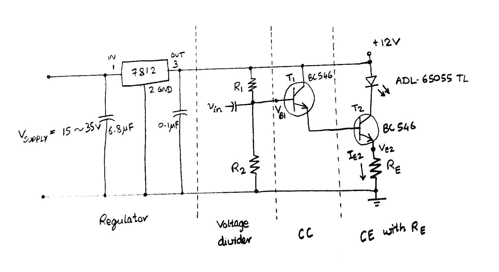
Normally, I use CE with RE configuration as a current source to drive LED as shown in the following figure. In this circuit, laser diode ADL-65055TL from Laser Components was used. Its operating current is 25mA, maximum current is 35mA, and operating voltage is 2.2V.
For a 12V power supply, assuming VCE(saturation) is approximately zero, RE is calculated as $$ R_E=\frac{Vcc-V_L}{I_{max}}=\frac{12-2.2}{35m}=280 \Omega $$ I did not want large gain for this CE configuration and bypass capacitor was not used. I wanted the ac output current of this class A amplifier to swing between 23mA and 29 mA. Using the quiescent emitter current for transister 2, IE2=26mA (near operating current), emitter voltage is, VE2=RE x Iop= 280 x 26m = 7.28V. To achieve high input impedance, a CC amplifier was cascaded in front as shown in the following figure. Assuming base-emitter junction voltage, VBE, as 0.7V, the quiescent base voltage of transister 1 is VB1= 7.28+0.7+0.7=8.68V. Neglecting the small base current, R1 and R2 are calculated as $$ V_{B1}=Vcc \times \frac{R_2}{R_1+ R_2}$$ $$ \frac{R_1}{R_2}+ 1=\frac{12}{8.68V}$$ Then, R2=2.6 R1. If we choose R1 as 22k arbitrarily, R2 will be 57k. The ac input voltage should be (29-23)m x 280= 1.68V peak to peak. The resulting prototype using available components in my lab is shown here.
Thursday, March 3, 2011
Capacitor selection for a Crystal Oscillator
A typical crystal oscillator circuit and an example layout design are shown in the figures. A crystal manufacturer normally specifies the load capacitance, CL, needed for a crystal in its datasheet. This value is the load seen by the crystal which is in series with C1 and C2, including all parasites. Typically, overall stray capacitance, Cstray, for pin, board, and PCB trace is between 2 pF and 7 pF. The relation between them can be represented by the following formula.
CL=(C1 * C2)/(C1 + C2) + Cstray
C1 and C2 are normally chosen to have equal value. Therefore,
C1 = C2=2 * (CL - Cstray)
For example, assume that Cstray is 4 pF and crystal load capacitance CL is 18 pF, C1 = C2= 28 pF. The normalized value of 30 pF can be used.
CL=(C1 * C2)/(C1 + C2) + Cstray
C1 and C2 are normally chosen to have equal value. Therefore,
C1 = C2=2 * (CL - Cstray)
For example, assume that Cstray is 4 pF and crystal load capacitance CL is 18 pF, C1 = C2= 28 pF. The normalized value of 30 pF can be used.
Monday, May 24, 2010
Astable Multivibrator using Op-amp
One of my friends wanted to calculate the oscillation frequency of an op-amp circuit. He had measured the output frequency of the circuit and it was 109 kHz. He asked my help to derive the relation between the oscillation frequency and its passive components. Although I have been away from analog circuits for a long time, I agreed to have a look. Then, he took the picture of circuit diagram using his hand phone and sent to me using MMS.
The basic idea behind the circuit is simple, so I calculated the frequency, took the following pictures using my hand phone and sent back to him.
Saturday, October 10, 2009
Multidrop network for RS232
I got a requirement to communicate one master device and eight slave devices. I intended to use RS485 half-duplex communication for this system but all devices happened to have only RS232 interfaces.
RS232 communication is a sort of communication that is to be used for one-to-one system. There is no problem if only the master device transmits and all slaves are receiving. The problem is that transmit lines of the slaves cannot be disabled and so that they cannot connect to the same line.
After analyzing the voltage signals, I have got an alternative solution to this problem. By adding a diode to the transmit line of each slave, I can use the system just like RS485 half-duplex communication. See the following figure for the hardware connection.
Updated: 2017 Sep 02
Thanks for all your comments. I have added more configurations according to your comments.
Updated: 2017 Sep 02
Thanks for all your comments. I have added more configurations according to your comments.
RS232 network with multiple masters and multiple slaves
UART/TTL-Serial network with single master and multiple slaves
If you are not using RS232 transceivers to change the physical signal voltages, the outputs of UARTs are still TTL level signals. In this case, you can connect multiple UARTs to a single master as follow.UART/TTL-Serial network with multiple masters and multiple slaves
Sunday, May 4, 2008
RS232-RS485 Converter
When you need to convert your serial communication from RS232 to RS422/RS485 or when you need to communicate to an RS485 device from a computer that uses RS232, you can use RS485 converter.
This kind of converters are easily available. As an example, IC-485SN bidirectional converter is shown in the following figures.
As shown in the first figure, this RS485 converter can be configured by using two switches.
The first switch is used to select device mode. If the RS232 side (where DB25 Female connector is located) is connected to a Computer or a Data Terminal Equipment, it must switch to DTE. If that side is connected to a modem or a device (data communication equipment), it must switch to DCE.
The second switch is used to select transmitting and receiving mode.
TxON, RxON is used for point to point operations. Transmit driver is always enabled and it is also always receiving. We can say, it is converting from RS232 to RS422. In RS232 side, RTS and CTS, DTR and DSR are loopback connected.
RS485 side connections are as follow:
TxRTS, RxON is used for multidrop operations. Although it is always receiving, transmit driver is enabled only when RTS is high. For a DCE, CTS must be used instead of RTS. It can be used as four wire RS485 full duplex communication. In RS232 side, RTS and CTS, DTR and DSR are loopback connected.
RS485 side connections are as follow:
TxDTR/RTS, RxDSR/ON is used for RS485 half duplex communication. For a DTE, transmit drivers for data lines and busy lines are enabled only when RTS is true. When DTR is true, busy signal will be transmitted. On the receiving side, DSR will be true when a busy signal is received. For a DCE, CTS must be used instead of RTS. And DTR and DSR are inverse. In RS232 side, only RTS and CTS are loopback connected.
RS485 side connections are as follow:
The connections for DB 9 female and DB25 male Cable are as follow
As shown in the first figure, this RS485 converter can be configured by using two switches.
The first switch is used to select device mode. If the RS232 side (where DB25 Female connector is located) is connected to a Computer or a Data Terminal Equipment, it must switch to DTE. If that side is connected to a modem or a device (data communication equipment), it must switch to DCE.
The second switch is used to select transmitting and receiving mode.
1. TxON, RxON Mode
TxON, RxON is used for point to point operations. Transmit driver is always enabled and it is also always receiving. We can say, it is converting from RS232 to RS422. In RS232 side, RTS and CTS, DTR and DSR are loopback connected.
RS485 side connections are as follow:
Pin 1 = Tx+
Pin 2 = Tx-
Pin 3 = Rx-
Pin 4 = Rx+
2. TxRTS, RxON Mode
TxRTS, RxON is used for multidrop operations. Although it is always receiving, transmit driver is enabled only when RTS is high. For a DCE, CTS must be used instead of RTS. It can be used as four wire RS485 full duplex communication. In RS232 side, RTS and CTS, DTR and DSR are loopback connected.
RS485 side connections are as follow:
Pin 1 = Tx+
Pin 2 = Tx-
Pin 3 = Rx-
Pin 4 = Rx+
3. TxDTR/RTS, RxDSR/ON Mode
TxDTR/RTS, RxDSR/ON is used for RS485 half duplex communication. For a DTE, transmit drivers for data lines and busy lines are enabled only when RTS is true. When DTR is true, busy signal will be transmitted. On the receiving side, DSR will be true when a busy signal is received. For a DCE, CTS must be used instead of RTS. And DTR and DSR are inverse. In RS232 side, only RTS and CTS are loopback connected.
RS485 side connections are as follow:
Pin 1 = Data+
Pin 2 = Data-
Pin 3 = Busy-
Pin 4 = Busy+
The connections for DB 9 female and DB25 male Cable are as follow
Female DB9 -------------- Male DB25
pin 1 ---------------------- pin 8 .......... Black
pin 2 ---------------------- pin 3 .......... Brown
pin 3 ---------------------- pin 2 .......... Red
pin 4 ---------------------- pin 20 ........ Orange
pin 5 ---------------------- pin 7 .......... Yellow
pin 6 ---------------------- pin 6 .......... Green
pin 7 ---------------------- pin 4 .......... Blue
pin 8 ---------------------- pin 5 .......... Magenta
pin 9 ---------------------- pin 22 ........ Gray
Wednesday, April 23, 2008
Using PC Serial Port
Controlling and using PC serial port using Visual Basic programming is discussed. Many computers have a serial port. If your computer does not have one, you can buy a USB to RS232 converter.
There are three topics to be discussed here.
1. Using VB6
2. Using VB2005 (VB.NET2)
3. Serial Port as IO
After OK has clicked, there will be MSComm control with a telephone icon in the Toolbox. Double click on this control to add it onto the Form. Its name will be "MSComm1" as shown below and you can change its settings in the Properties box near the bottom right corner.
In this example, its settings will not be changed in its properties box. But they will be changed in "Form_Load()" event. Double click on any blank space on the form to write in Form_Load() event as shown in the following code.
The setting "9600,N,8,1" means that we will use Baud rate 9600, No parity, 8 data bit and 1 stop bit. RThreshold defines number of bytes in receive buffer to trigger receive event. In this example, Receive Event will be triggered even if there is only one byte in receive buffer. Comm port 1 of PC is used and opened here. A textbox is used to display the receive data. Another textbox and a Command button are added to the form to send data. Caption property of the Command button is changed to 'Send'.
Double click on that button and write the following code in its click event function.
Everytime the button is clicked, the data "ABCD" will be sent from the serial port. You can replace ABCD with any data you want to send. To receive data, OnComm event of MSComm control is used. Double click on MSComm control and write the following code in its event function. If OnComm Event is a data received event -comEvReceive, the Textbox will be updated with received data.
After that, program will be as shown in the following figure.
Try to run the program. Data will be sent when the Send button is clicked.
In VB2005, using Serial port is easier because SerialPort control is already in the toolbox. Create a Windows Application from File Menu -> New Project command. Double click on SerialPort Control in the Toolbox to add it onto the form.
Select the control and change its properties in the properties box. In the example, Name will be SerialPort1, BaudRates will be 9600, Databits will be 8, Parity will be None and StopBits will be One. ReceivedBytesThreshold defines number of bytes in receive buffer to trigger receive event. In this example, Receive Event will be triggered even if there is only one byte in receive buffer. Therefore ReceivedBytesThreshold will be 1. Comm port 1 of PC is used and PortName will be set to COM1.
Double click on the Form and write the following code in the Form Load Event.
By doing so, the comm port will be opened at the program start. Normal Encoding of serial port control is ASCII. You can also change Encoding at the Form Load Event as follow.
Add a Button to send data and a TextBox to display received data. Change Text property of the Button to Send. Double click on the Button and write the following code in its click event.
Everytime, the button is clicked, the data "ABCD" will be sent. You can replace ABCD with any data you want to send. To receive data, write the following code in the DataReceived event of SerialPort1.
If you want to read the received data byte by byte, the following code can also be used.
After that, the program will be as follow.
Then, you can try the program to send and receive data.
Sending Binary Data
The example above is for character data. For binary data whose ASCII code number greater than 127 can be manipulated as follow.
ReadChar cannot be used to receive binary data. ReadByte can be used instead as in the following example.
Getting Port List in Your PC
To list the all ports in your PC in a Combo box and to select the port number that had been saved in user setting, you can used the following code.
Related post:
There are three topics to be discussed here.
1. Using VB6
2. Using VB2005 (VB.NET2)
3. Serial Port as IO
Using VB6
MSComm ActiveX contorl can be used in VB6 to communicate through a serial port. Create a New project by selecting Standard Exe. Go to Project Menu and select Components command. Add Microsoft Comm Control 6.0 from Components dialog.
After OK has clicked, there will be MSComm control with a telephone icon in the Toolbox. Double click on this control to add it onto the Form. Its name will be "MSComm1" as shown below and you can change its settings in the Properties box near the bottom right corner.
In this example, its settings will not be changed in its properties box. But they will be changed in "Form_Load()" event. Double click on any blank space on the form to write in Form_Load() event as shown in the following code.
Private Sub Form_Load()
MSComm1.Settings = "9600,N,8,1"
MSComm1.RThreshold = 1
MSComm1.CommPort = 1
MSComm1.PortOpen = True
Text1.Text = ""
End Sub
The setting "9600,N,8,1" means that we will use Baud rate 9600, No parity, 8 data bit and 1 stop bit. RThreshold defines number of bytes in receive buffer to trigger receive event. In this example, Receive Event will be triggered even if there is only one byte in receive buffer. Comm port 1 of PC is used and opened here. A textbox is used to display the receive data. Another textbox and a Command button are added to the form to send data. Caption property of the Command button is changed to 'Send'.
Double click on that button and write the following code in its click event function.
Private Sub Command1_Click()
MSComm1.Output = "ABCD"
End Sub
Everytime the button is clicked, the data "ABCD" will be sent from the serial port. You can replace ABCD with any data you want to send. To receive data, OnComm event of MSComm control is used. Double click on MSComm control and write the following code in its event function. If OnComm Event is a data received event -comEvReceive, the Textbox will be updated with received data.
Private Sub MSComm1_OnComm()
If MSComm1.CommEvent = comEvReceive Then
Text1.Text = Text1.Text & MSComm1.Input
End If
End Sub
After that, program will be as shown in the following figure.
Try to run the program. Data will be sent when the Send button is clicked.
Using VB2005
In VB2005, using Serial port is easier because SerialPort control is already in the toolbox. Create a Windows Application from File Menu -> New Project command. Double click on SerialPort Control in the Toolbox to add it onto the form.
Select the control and change its properties in the properties box. In the example, Name will be SerialPort1, BaudRates will be 9600, Databits will be 8, Parity will be None and StopBits will be One. ReceivedBytesThreshold defines number of bytes in receive buffer to trigger receive event. In this example, Receive Event will be triggered even if there is only one byte in receive buffer. Therefore ReceivedBytesThreshold will be 1. Comm port 1 of PC is used and PortName will be set to COM1.
Double click on the Form and write the following code in the Form Load Event.
CheckForIllegalCrossThreadCalls = False
SerialPort1.Open()
By doing so, the comm port will be opened at the program start. Normal Encoding of serial port control is ASCII. You can also change Encoding at the Form Load Event as follow.
SerialPort1.Encoding = System.Text.Encoding.Default
Add a Button to send data and a TextBox to display received data. Change Text property of the Button to Send. Double click on the Button and write the following code in its click event.
SerialPort1.Write("ABCD")
Everytime, the button is clicked, the data "ABCD" will be sent. You can replace ABCD with any data you want to send. To receive data, write the following code in the DataReceived event of SerialPort1.
TextBox1.Text &= SerialPort1.ReadExisting()
If you want to read the received data byte by byte, the following code can also be used.
Dim n As Int32
Dim i As Int32
Dim cmd As String
Dim c As String
n = SerialPort1.BytesToRead
For i = 1 To n
c = Chr(SerialPort1.ReadChar())
cmd &= c
Next
TextBox1.Text &= cmd
After that, the program will be as follow.
Then, you can try the program to send and receive data.
Sending Binary DataThe example above is for character data. For binary data whose ASCII code number greater than 127 can be manipulated as follow.
Dim a(3) As Byte
a(0) = &H41
a(1) = &H31
a(2) = &HFF
a(3) = &H80
SerialPort1.Write(a, 0, 4)
ReadChar cannot be used to receive binary data. ReadByte can be used instead as in the following example.
Dim n As Int32
Dim i As Int32
Dim cmd As String = ""
Dim c As String
n = SerialPort1.BytesToRead
For i = 1 To n
c = Chr(SerialPort1.ReadByte())
cmd &= c
Next
TextBox1.Text &= cmd
Getting Port List in Your PC
To list the all ports in your PC in a Combo box and to select the port number that had been saved in user setting, you can used the following code.
Dim ports As String() = SerialPort.GetPortNames()
Dim port As String
Array.Sort(ports)
cmbSerial.Items.Clear()
For Each port In ports
cmbSerial.Items.Add(port)
Next port
Dim index As Integer
index = cmbSerial.FindString(My.Settings.MCOM)
cmbSerial.SelectedIndex = index
Using Serial Port as IO
Besides Tx and Rx to send and receive data, there are two control outputs and four status inputs in a serial. RTS and DTR can be used as outputs. CTS, DSR, CD and RI can be used as inputs. If you don't need a lot of I/O in an application, serial port is a good choice for IO interface.Related post:
Saturday, April 19, 2008
Asynchronous Serial Communication- RS232, RS422 and RS485
In serial communication, data bytes are sent bit by bit. Its advantage is that data can be sent using only one wire instead of using many parallel wires. But it needs a UART to convert data byte to serial bit stream.
UART not only converts data into serial bit stream, but it also format the bit stream into Asynchronous Serial Communication Protocol by inserting start bit, parity bit, stop bits, etc.
In idle state, a UART normally puts its output in 1. The receiving UART needs to differentiate whether the 1 is data to receive or idle state to ignore. Start bit is used to solve this problem. Normally, a UART ignore 1 as idle. After it received the first 0 as start bit, it accepts the following bits as data for predefined number of bits.
The rate of sending data unit is called Baud rate. For example, if the baud rate is 1 kHz, time period to send each data bit is 1/(1kHz)= 1 ms. A popular baud rate is 9600.
The number of data bits for sending UART and receiving UART must be the same. It can be from 5 bit data to 8 bit data. For example, ASCII data are normally sent with 7 bits. LSB is sent first. A popular number of data bits is 8.
Parity bit is used to check the integrity of the data. In even parity, the number of 1 in data bits and the parity bit itself is even. In odd parity, it is odd. Typically, parity bit is not used.
Stop bit is used to separate the consecutive data bytes. The number of stop bit can be 1,2, etc. 1 is used as a stop bit. Stop bits are sent after sending data bits and parity bits. A popular number of stop bit is 1.
The following example send the data byte 0x41 using 9600, 8N1. That means
Baud rate = 9600
Data bit = 8 bits
Parity = No parity (N= No parity, E= Even parity, O= Odd parity)
Stop bit= 1 stop bit
Since it is no parity, stop bit will come immediately after data bit without any parity bit.
A UART can be in many different forms. The first one is in the form of a discrete IC. A popular IC is 16550. For CMOS, it will become 16C550, and so on. It has its own buffer and interrupt mechanisms. Therefore, it is easy to use. Serial data comes out from sout pin. Its basic configuration is as shown in the following diagram.
Another form of UART is built-in UART within a microcontroller. The last form of UART is software UART that uses IO pins to emulate it.
A UART uses 5V output to represent 1 and uses 0V output to represent 0. To connect to external devices, these output voltages are normally converted into suitable signaling levels by using a transceiver. A popular signaling standard is RS232. A RS232 transceiver outputs or inputs -10V for 1 and +10V for 0. Valid voltage range is from +/- 3V to +/-25V. A popular transceiver IC is MAX232. Its configuration is shown in the following diagram.
If you want to use smaller capacitor (0.1uF) and smaller IC, you can use MAX202. To use MAX202 with 16C550, connect sout pin of UART which produces 0V and 5V to its pin 11. Then Tx will come out from pin 14 as +10V and -10V. Similarly, +10V and -10V received from Rx line that is connected to pin 13 will come out as 0V and 5V from pin 12 which connects to sin of UART.
The following figure shows typical connection for RS232.
You can use a multimeter to differentiate Tx and Rx of opened RS232 lines. Typically, the voltage between Tx and Ground is -10V and there is no voltage between Rx and Ground. RS232 is said unbalanced lines.
In RS232 communication, besides data transmit line (Tx) and data receive line (Rx), there are also control and status lines for handshaking. Among Primary Communication lines, Tx and RTS are outputs and Rx and CTS are inputs. Among Status and Control lines, DTR is output while DSR and CD are inputs. They will be discussed further. When we talk about RS232 devices, DTE ( Data Terminal Equipment) refers to computer and DCE (Data Circuit-Terminating Equipment) refers to Modem or device.
RTS- Request To Send signal is requested by DTE to DCE. It is normally logic 1 (negative voltage) and when requested it becomes logic 0 (positive voltage).
CTS- Clear To Send signal is used by DCE to infrom DTE that it is ready to receive. It is normally logic 1 (negative voltage) and it becomes logic 0 (positive voltage) when asserted.
DSR- DCE Ready (Data Set Ready) is used by DCE (device) to inform DTE that it has turned on and is ready. It is normally logic 1 (negative voltage) and it becomes logic 0 (positive voltage) when asserted.
DTR- DTE Ready is asserted by DTE to inform DCE that it want to communicate. It is normally logic 1 (negative voltage) and it becomes logic 0 (positive voltage) when asserted.
CD- Carrier Detect (Received Line Signal Detector) is used when DCE is a modem. When this modem receives the answer tone of a modem at the other side of the telephone line, it asserts the computer with logic 0.
RI- Ring Indicator is asserted when a modem receives ring signal. It outputs logic 0 to the computer. It is positive only when there is ring signal. It is negative between ring signals and when there is no ring signal.
Let us continue to discuss about RS232 wire connectors.
As shown in the following figure, a computer (DTE) has Male DB9 connector for RS232 and a device (DCE) has Female DB9 connector. Pin connection for a male connector is shown.
Pin connection of a female connector is also shown below.
RS422 and RS485 function using the difference voltage between two wires. Transmit voltage is between +12V and -12V and they can receive even if the voltage difference is about 0.4V. The voltage between +Tx and -Tx is output voltage and the voltage between +Rx and -Rx is input voltage. They are called balance line because they don't use the voltage between ground and transmit line. They have more resistance to common mode noise. Therefore, they can communicate faster and can communicate over longer distance.
Note:
-200mV to +200mV = 0.4 V
-6V to +6V = 12V
Both RS232 and RS422 can have many receivers on a single bus line but they can have only one transmitter on a bus line. In RS485, transmit driver circuit can be enabled and disabled by using data enable line. As a result, it can have many receivers and transmitters on a bus line. Normally, RS422 uses two wires (+Tx, -Tx) for transmitting and another two wires (+Rx, -Rx) for receiving. Therefore, RS422 uses total of four wires. RS485 can communicate using only two wires for both transmitting and receiving in half duplex mode. RS485 can also be used in Full duplex mode using four wires. The following figure shows a typical connection for RS485 using MAX481 transceiver IC. It has only two wires to use in half duplex mode.
An example using MAX491 to connect RS485 in full duplex mode is shown below. If you connect +Tx and +Rx and at the same time -Tx and -Rx, it can be used in half duplex mode.
Actually, full duplex RS485 with four wires whose transmit driver circuit always enabled is same as RS422. RS422 is normally used to extend distance of RS232 communication. When the distance is too far to use RS232, RS422 converter can be used in transmitting side and receiving side can convert the signal back to RS232.
In case, you want to use RS422/RS485 input device with RS232 output device without converter, you can directly connect RS232 Tx output to RS422/RS485 -Rx and RS232 GND to +Rx line. I tried it once before and it was OK. RS422, RS485 half duplex and RS485 full duplex connections are shown below. The first one is RS422 which can be used for only one to one connection. There can be many receivers, but there can only be one transmitter in a bus line. We cannot control transmit driver.
Note that RS485 half duplex has driver enable and receiver enable. Typically, there can be up to 32 node in a bus line.
RS485 full duplex.
UART not only converts data into serial bit stream, but it also format the bit stream into Asynchronous Serial Communication Protocol by inserting start bit, parity bit, stop bits, etc.
In idle state, a UART normally puts its output in 1. The receiving UART needs to differentiate whether the 1 is data to receive or idle state to ignore. Start bit is used to solve this problem. Normally, a UART ignore 1 as idle. After it received the first 0 as start bit, it accepts the following bits as data for predefined number of bits.
The rate of sending data unit is called Baud rate. For example, if the baud rate is 1 kHz, time period to send each data bit is 1/(1kHz)= 1 ms. A popular baud rate is 9600.
The number of data bits for sending UART and receiving UART must be the same. It can be from 5 bit data to 8 bit data. For example, ASCII data are normally sent with 7 bits. LSB is sent first. A popular number of data bits is 8.
Parity bit is used to check the integrity of the data. In even parity, the number of 1 in data bits and the parity bit itself is even. In odd parity, it is odd. Typically, parity bit is not used.
Stop bit is used to separate the consecutive data bytes. The number of stop bit can be 1,2, etc. 1 is used as a stop bit. Stop bits are sent after sending data bits and parity bits. A popular number of stop bit is 1.
The following example send the data byte 0x41 using 9600, 8N1. That means
Baud rate = 9600
Data bit = 8 bits
Parity = No parity (N= No parity, E= Even parity, O= Odd parity)
Stop bit= 1 stop bit
Since it is no parity, stop bit will come immediately after data bit without any parity bit.
Forms of UART
A UART can be in many different forms. The first one is in the form of a discrete IC. A popular IC is 16550. For CMOS, it will become 16C550, and so on. It has its own buffer and interrupt mechanisms. Therefore, it is easy to use. Serial data comes out from sout pin. Its basic configuration is as shown in the following diagram.
Another form of UART is built-in UART within a microcontroller. The last form of UART is software UART that uses IO pins to emulate it.
RS232
A UART uses 5V output to represent 1 and uses 0V output to represent 0. To connect to external devices, these output voltages are normally converted into suitable signaling levels by using a transceiver. A popular signaling standard is RS232. A RS232 transceiver outputs or inputs -10V for 1 and +10V for 0. Valid voltage range is from +/- 3V to +/-25V. A popular transceiver IC is MAX232. Its configuration is shown in the following diagram.
If you want to use smaller capacitor (0.1uF) and smaller IC, you can use MAX202. To use MAX202 with 16C550, connect sout pin of UART which produces 0V and 5V to its pin 11. Then Tx will come out from pin 14 as +10V and -10V. Similarly, +10V and -10V received from Rx line that is connected to pin 13 will come out as 0V and 5V from pin 12 which connects to sin of UART.
The following figure shows typical connection for RS232.
You can use a multimeter to differentiate Tx and Rx of opened RS232 lines. Typically, the voltage between Tx and Ground is -10V and there is no voltage between Rx and Ground. RS232 is said unbalanced lines.
In RS232 communication, besides data transmit line (Tx) and data receive line (Rx), there are also control and status lines for handshaking. Among Primary Communication lines, Tx and RTS are outputs and Rx and CTS are inputs. Among Status and Control lines, DTR is output while DSR and CD are inputs. They will be discussed further. When we talk about RS232 devices, DTE ( Data Terminal Equipment) refers to computer and DCE (Data Circuit-Terminating Equipment) refers to Modem or device.
RTS- Request To Send signal is requested by DTE to DCE. It is normally logic 1 (negative voltage) and when requested it becomes logic 0 (positive voltage).
CTS- Clear To Send signal is used by DCE to infrom DTE that it is ready to receive. It is normally logic 1 (negative voltage) and it becomes logic 0 (positive voltage) when asserted.
DSR- DCE Ready (Data Set Ready) is used by DCE (device) to inform DTE that it has turned on and is ready. It is normally logic 1 (negative voltage) and it becomes logic 0 (positive voltage) when asserted.
DTR- DTE Ready is asserted by DTE to inform DCE that it want to communicate. It is normally logic 1 (negative voltage) and it becomes logic 0 (positive voltage) when asserted.
CD- Carrier Detect (Received Line Signal Detector) is used when DCE is a modem. When this modem receives the answer tone of a modem at the other side of the telephone line, it asserts the computer with logic 0.
RI- Ring Indicator is asserted when a modem receives ring signal. It outputs logic 0 to the computer. It is positive only when there is ring signal. It is negative between ring signals and when there is no ring signal.
Let us continue to discuss about RS232 wire connectors.
As shown in the following figure, a computer (DTE) has Male DB9 connector for RS232 and a device (DCE) has Female DB9 connector. Pin connection for a male connector is shown.
pin 1 = CD- Carrier Detect (input)
pin 2 = Rx- Receive Data (input)
pin 3 = Tx- Transmit Data (output)
pin 4 = DTR- Data Terminal Ready (output)
pin 5 = GND- System Ground
pin 6 = DSR- Data Set Ready (input)
pin 7 = RTS- Request To Send (output)
pin 8 = CTS- Clear To Send (input)
pin 9 = RI - Ring Indicator (input)
Pin connection of a female connector is also shown below.
pin 1 = CD- Carrier Detect (output)
pin 2 = Tx- Transmit Data (output)
pin 3 = Rx- Receive Data (input)
pin 4 = DTR- Data Terminal Ready (input)
pin 5 = GND- System Ground
pin 6 = DSR- Data Set Ready (output)
pin 7 = CTS- Clear To Send (input)
pin 8 = RTS- Request To Send (output)
pin 9 = RI - Ring Indicator (output
RS422 and RS485
RS422 and RS485 function using the difference voltage between two wires. Transmit voltage is between +12V and -12V and they can receive even if the voltage difference is about 0.4V. The voltage between +Tx and -Tx is output voltage and the voltage between +Rx and -Rx is input voltage. They are called balance line because they don't use the voltage between ground and transmit line. They have more resistance to common mode noise. Therefore, they can communicate faster and can communicate over longer distance.
Note:
-200mV to +200mV = 0.4 V
-6V to +6V = 12V
Both RS232 and RS422 can have many receivers on a single bus line but they can have only one transmitter on a bus line. In RS485, transmit driver circuit can be enabled and disabled by using data enable line. As a result, it can have many receivers and transmitters on a bus line. Normally, RS422 uses two wires (+Tx, -Tx) for transmitting and another two wires (+Rx, -Rx) for receiving. Therefore, RS422 uses total of four wires. RS485 can communicate using only two wires for both transmitting and receiving in half duplex mode. RS485 can also be used in Full duplex mode using four wires. The following figure shows a typical connection for RS485 using MAX481 transceiver IC. It has only two wires to use in half duplex mode.
An example using MAX491 to connect RS485 in full duplex mode is shown below. If you connect +Tx and +Rx and at the same time -Tx and -Rx, it can be used in half duplex mode.
Actually, full duplex RS485 with four wires whose transmit driver circuit always enabled is same as RS422. RS422 is normally used to extend distance of RS232 communication. When the distance is too far to use RS232, RS422 converter can be used in transmitting side and receiving side can convert the signal back to RS232.
In case, you want to use RS422/RS485 input device with RS232 output device without converter, you can directly connect RS232 Tx output to RS422/RS485 -Rx and RS232 GND to +Rx line. I tried it once before and it was OK. RS422, RS485 half duplex and RS485 full duplex connections are shown below. The first one is RS422 which can be used for only one to one connection. There can be many receivers, but there can only be one transmitter in a bus line. We cannot control transmit driver.
Note that RS485 half duplex has driver enable and receiver enable. Typically, there can be up to 32 node in a bus line.
RS485 full duplex.
Subscribe to:
Posts (Atom)