
Thursday, May 5, 2011
Degrees of Freedom of the Human Arm
Have you ever think how many degrees of freedom the human arm has (excluding palm and fingers)? I would like to share a short excerpt from a book by Saeed Benjamin Niku, Introduction to Robotics -Analysis, Control, Applications.
The shoulder, the elbow, and the wrist are three joint clusters in the human arm.
The shoulder has 3 degrees of freedom.
The upper arm can swing up and down in the coronal plane.
It can also swing back and forth in the transverse plane.
And rotation with respective to the axis along humerus can be done also.
The following is the illustration of human anatomy planes from Wikipedia.
 The elbow has only 1 degree of freedom- flexing and extending.
The wrist has 3 degrees of freedom -up and down, and side to side, and rotation of forearm with respective to the axis along ulna.
Therefore, the human arm has a total of 7 degrees of freedom.


Tuesday, May 3, 2011
Byte Stuffing
I occasionally need to write programs to send and receive data bytes from one device to another. That is why I arbitrarily choose a simple variant of byte stuffing methods to build frames to send and receive data. To delimit the frame, control characters - 0x02 and 0x03- are defined as start of text (STX) and end of text (ETX) respectively. For error detection, exclusive-or of data bytes is appended after the ETX as a checksum. If you need better error detection, CRC as described at
CRC Calculation in VB and C
can also be used.
For example, if we want to send two bytes of data -
Byte Stuffing on GitHub
The following is the C++ code to build, send and receive a frame.
CRC Calculation in VB and C
can also be used.
For example, if we want to send two bytes of data -
0x30 0x31,the resulting frame will be
0x02 0x30 0x31 0x03 0x01,where 0x02 at the start is added as STX, followed by data bytes and the byte before the last one, 0x03, is added as ETX. Since the exclusive-or of data bytes, 0x02^0x03, is 0x01, it is appended at the end as checksum. How can we send data that contains 0x02 or 0x03 which were already used as control characters? We need to define another control character 0x10 as Data Link Escape (DLE) to mark data that are not control characters. As an another example, let us build a frame for five data bytes -
0x30 0x02 0x65 0x10 0x03.We will do byte stuffing by putting DLE in front of every data byte that conflicts with STX, ETX, or DLE. And
0x02 0x30 0x10 0x02 0x65 0x10 0x10 0x10 0x03 0x03 0x44will be the resulting frame. I have developed a few programs in C and LabVIEW. Example programs can be downloaded at the following links.
Byte Stuffing on GitHub
The following is the C++ code to build, send and receive a frame.
// Byte stuffing- sending and receiving frames // Author: Yan Naing Aye #ifndef FRAME_H #define FRAME_H #include#define STX 0x02 #define ETX 0x03 #define DLE 0x10 #define TX_BUF_SIZE 128 #define RX_BUF_SIZE 128 enum RX_STATE { IGNORE,RECEIVING,ESCAPE,RXCRC1,RXCRC2 }; //----------------------------------------------------------------------------- class Frame { RX_STATE rState; protected: int TxN;//number of transmitting bytes int RxN;//number of receiving bytes char tb[TX_BUF_SIZE];//transmit buffer char rb[RX_BUF_SIZE];//receiving data public: Frame(); int setTxFrame(char* d,int n); unsigned int CRC16CCITT_Calculate(char* s,unsigned char len,unsigned int crc); int getTxN(); int getRxN(); int receiveRxFrame(char c);//get receiving frame from received char char* getTxBuf(); char* getRxBuf(); }; //----------------------------------------------------------------------------- Frame::Frame():TxN(0),RxN(0),rState(IGNORE){} //----------------------------------------------------------------------------- char* Frame::getTxBuf(){ return tb; } //----------------------------------------------------------------------------- char* Frame::getRxBuf(){ return rb; } //----------------------------------------------------------------------------- //Prepare transmitting frame int Frame::setTxFrame(char* d,int n) { unsigned int txcrc=0xFFFF;//initialize crc char c; int i=0,j=0; tb[i++]=STX;//start of frame for(j=0;j < n;j++) { c=d[j]; if((c==STX)||(c==ETX)||(c==DLE)) tb[i++]=(DLE); tb[i++]=c; } tb[i++]=(ETX);//end of frame txcrc=CRC16CCITT_Calculate(d,n,txcrc);//calculate crc tb[i++]=txcrc & 0xFF; tb[i++]=(txcrc >> 8) & 0xFF; TxN=i; return TxN; } //----------------------------------------------------------------------------- //Inputs //s : pointer to input char string //len: string len (maximum 255) //crc: initial CRC value //Output //Returns calculated CRC unsigned int Frame::CRC16CCITT_Calculate(char* s,unsigned char len,unsigned int crc) { //CRC Order: 16 //CCITT(recommendation) : F(x)= x16 + x12 + x5 + 1 //CRC Poly: 0x1021 //Operational initial value: 0xFFFF //Final xor value: 0 unsigned char i,j; for(i=0;i < len;i++,s++) { crc^=((unsigned int)(*s) & 0xFF) << 8; for(j=0;j<8;j++) { if(crc & 0x8000) crc=(crc << 1)^0x1021; else crc <<=1; } } return (crc & 0xFFFF);//truncate last 16 bit } //----------------------------------------------------------------------------- //get number of transmitting bytes int Frame::getTxN() { return TxN; } //----------------------------------------------------------------------------- //get number of transmitting bytes int Frame::getRxN() { return RxN; } //----------------------------------------------------------------------------- //process receiving char int Frame::receiveRxFrame(char c) { static char b; unsigned int crc; unsigned int rxcrc=0xFFFF;//initialize CRC switch(rState){ case IGNORE: if(c==STX) { rState=RECEIVING;RxN=0;} break; case RECEIVING: if(c==STX) { rState=RECEIVING;RxN=0;} else if(c==ETX){rState=RXCRC1;} else if(c==DLE){ rState=ESCAPE; } else { rb[RxN++]=c; } break; case ESCAPE: rb[RxN++]=c; rState=RECEIVING; break; case RXCRC1: b=c; rState=RXCRC2; break; case RXCRC2: rState=IGNORE; crc=( (int)c << 8 | ((int)b & 0xFF) ) & 0xFFFF;//get received crc rxcrc=CRC16CCITT_Calculate(rb,RxN,rxcrc);//calculate crc //printf("crc: %x rxcrc:%x \n",crc,rxcrc); if(rxcrc==crc){return RxN;}//if crc is correct else {RxN=0;}//discard the frame break; } return 0; } //----------------------------------------------------------------------------- //############################################################################# class Frame2:public Frame { char Dt[20];//transmitting data public: Frame2(); void printTxFrame(); void printRxFrame(); void printRxData(); void setTxData(float x,float y,float z,float b,float t); }; //----------------------------------------------------------------------------- Frame2::Frame2():Frame(),Dt(""){} //----------------------------------------------------------------------------- //Print out frame content void Frame2::printTxFrame() { printf("Tx frame buffer: "); for(int j=0;j < TxN;j++) printf("%02X ",(unsigned char)tb[j]); printf("\n"); } //----------------------------------------------------------------------------- //Print out frame content void Frame2::printRxFrame() { printf("Rx data buffer: "); for(int j=0;j < RxN;j++) printf("%02X ",(unsigned char)rb[j]); printf("\n"); } //----------------------------------------------------------------------------- //Set transmitting data void Frame2::setTxData(float x,float y,float z,float b,float t) { *(float*)(Dt)=x; *(float*)(Dt+4)=y; *(float*)(Dt+8)=z; *(float*)(Dt+12)=b; *(float*)(Dt+16)=t; Frame::setTxFrame(Dt,20); } //----------------------------------------------------------------------------- //Print out received data void Frame2::printRxData() { float x,y,z,b,t; x=*(float*)(Dt); y=*(float*)(Dt+4); z=*(float*)(Dt+8); b=*(float*)(Dt+12); t=*(float*)(Dt+16); printf("Rx data: %f %f %f %f %f \n",x,y,z,b,t); } //----------------------------------------------------------------------------- #endif // FRAME_H
Friday, March 4, 2011
Simple 6 DOF Translation and Rotation Stages
I had the requirement to control a device in 6 degrees of freedom (DOF). There were 3 motorized translation stages to control the position of the tool in 3D space and 3 rotary motorized stages to control its orientation. Although it could be thought as a robot arm having 3 prismatic joints and 3 revolute joints, I did not want to involve complex forward and inverse kinematics for this simple testing equipment.
Here is an example transformation. By arranging rotational axes of rotary motorized stages to intersect at the tool, a simple direct 6 DOF control could be achieved. The following figures show schematic diagram and 3D drawing for the equipment that I designed.

Here is an example transformation. By arranging rotational axes of rotary motorized stages to intersect at the tool, a simple direct 6 DOF control could be achieved. The following figures show schematic diagram and 3D drawing for the equipment that I designed.


Thursday, March 3, 2011
Capacitor selection for a Crystal Oscillator
A typical crystal oscillator circuit and an example layout design are shown in the figures. A crystal manufacturer normally specifies the load capacitance, CL, needed for a crystal in its datasheet. This value is the load seen by the crystal which is in series with C1 and C2, including all parasites. Typically, overall stray capacitance, Cstray, for pin, board, and PCB trace is between 2 pF and 7 pF. The relation between them can be represented by the following formula.
CL=(C1 * C2)/(C1 + C2) + Cstray
C1 and C2 are normally chosen to have equal value. Therefore,
C1 = C2=2 * (CL - Cstray)
For example, assume that Cstray is 4 pF and crystal load capacitance CL is 18 pF, C1 = C2= 28 pF. The normalized value of 30 pF can be used.

CL=(C1 * C2)/(C1 + C2) + Cstray
C1 and C2 are normally chosen to have equal value. Therefore,
C1 = C2=2 * (CL - Cstray)
For example, assume that Cstray is 4 pF and crystal load capacitance CL is 18 pF, C1 = C2= 28 pF. The normalized value of 30 pF can be used.


Tuesday, February 22, 2011
Denavit-Hartenberg Representation of Robots
The D-H model of representation is a simple way of modeling robot links and joints that can be used for any robot configuration.
We will have to assign a z-axis and an x-axis for each link. The D-H representation does not use the y-axis at all. Let Lk be the frame associated with link k.


For simulation, a nice free software called Robotassist can be downloaded at www.kinematics.com
Ref:
Introduction to Robotics -Analysis, Control, Applications; Second Edition, Saeed Benjamin Niku
Fundamental of Robotics -Analysis & Control, Robert J. Schilling

1. Define Z Axis from All Joints
From the axis of joint k+1, define the zk axis for link k. If the joint is revolute, the z axis is in the direction of rotation as followed by the right hand rule for the rotations. If the joint is prismatic, the z-axis for the joint is along the direction of the linear movement.2. Define Origins
The intersection of the zk and zk-1 axes is selected as the origin of Lk . If they do not intersect, use the intersection of zk with a common normal between zk and zk-1. There is always one line mutually perpendicular to any two skew lines, called common normal, which is the shortest distance between them.3. Define X-axis
Assign xk in the direction of the common normal between zk and zk-1. If z-axes are intersecting, select xk to be orthogonal to both zk and zk-1 (the direction of the cross-product of the two z-axes). If zk and zk-1 are parallel, point xk away from zk-1 colinear with the common normal of the previous joint.4. Define Y-axis
Select yk to form a right-handed orthonormal coordinate frame Lk.5. Define the Four Kinematic Parameters
*θk is defined as the angle between xk-1 and xk axes about the zk-1 axis. *dk is the distance between xk-1 and xk axes along zk-1 axis. *ak is the distance between zk-1 and zk axes along xk axis. *αk is the angle between zk-1 and zk axes about xk axis.6. Transferring Frame k-1 to Frame k
*Rotation of Lk-1 about the zk-1 axis by θk will make xk-1 and xk parallel to each other. This is true because the common normals ak-1 and ak are both perpendicular to zk-1 axis. *Translation of Lk-1 along zk-1 axis a distance of dk will make xk-1 and xk colinear. *Translation of Lk-1 along xk axis a distance of ak will bring the origins of Lk-1 and Lk together. *Rotation of Lk-1 about xk axis by αk will make zk-1 and zk axes parallel. At this point, frames Lk-1 and Lk will be exactly the same.

For simulation, a nice free software called Robotassist can be downloaded at www.kinematics.com
Ref:
Introduction to Robotics -Analysis, Control, Applications; Second Edition, Saeed Benjamin Niku
Fundamental of Robotics -Analysis & Control, Robert J. Schilling
Thursday, December 30, 2010
Inkscape
Inkscape is a vector graphic editor similar to Illustrator or CorelDraw. Inkscape is better in the sense of cost because it is free. It is also an open source software.
It can be downloaded for free at http://inkscape.org/
The nice feature is that graphics can be saved in pdf format. It allows high quality graphics when you use it with pdflatex to produce pdf files. Since they are Scalable Vector Graphics, unlike bitmap images, there is no problem even when they are magnified.
The following is an Inkscape example to draw a line with arrow head. 1. Select Bezier Curves tool. Click to start a line. Double click (or click then press enter key) to end the line. 2. Click Fill and Stroke... command under Object menu (or click Fill: or Stroke: near lower left corner). In the Stroke style tab, change End Markers to arrow. 3. Line color can also be changed in Stroke paint tab. Click Extensions->Modify Path->Color Markers to Match Stroke to change the arrow head color also. To insert math symbols, you can press ctrl+u and type the hexadecimal Unicode code point of the symbol in a text box. Then, press enter.
http://wiki.inkscape.org/wiki/index.php/FAQ
http://www.unicode.org/charts/PDF/U0370.pdf
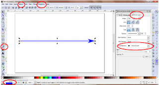
The following is an Inkscape example to draw a line with arrow head. 1. Select Bezier Curves tool. Click to start a line. Double click (or click then press enter key) to end the line. 2. Click Fill and Stroke... command under Object menu (or click Fill: or Stroke: near lower left corner). In the Stroke style tab, change End Markers to arrow. 3. Line color can also be changed in Stroke paint tab. Click Extensions->Modify Path->Color Markers to Match Stroke to change the arrow head color also. To insert math symbols, you can press ctrl+u and type the hexadecimal Unicode code point of the symbol in a text box. Then, press enter.
http://wiki.inkscape.org/wiki/index.php/FAQ
http://www.unicode.org/charts/PDF/U0370.pdf

Monday, July 12, 2010
Random Password Generator
I have a few nagging computer user accounts that regularly ask me to change password. Some of them even remember history of about ten old passwords to prevent me from using them again.
As a side effect, I have to think of new passwords again and again. Later, I use random password generators that are freely available on the Internet. Just for fun, I have also developed a random password generator of my own and you can see it at the following link.
Source PHP file
Ref: http://en.wikipedia.org/wiki/Password_generator
As a side effect, I have to think of new passwords again and again. Later, I use random password generators that are freely available on the Internet. Just for fun, I have also developed a random password generator of my own and you can see it at the following link.
Source PHP file
Ref: http://en.wikipedia.org/wiki/Password_generator
Friday, June 18, 2010
Common Interrupt Pitfalls
I just want to share some interesting facts that I found in SDCC Compiler User Guide.
From my experience, I think these facts are very important to keep in mind of a firmware programmer. Last time, I got an experience that my program executed wrongly even though I could not find any fault in my program. Suddenly, I remembered stack overflow problem and the program worked correctly after I changed the stack size.
Variable not declared volatile
If an interrupt service routine changes variables which are accessed by other functions these variables have to be declared volatile. See http://en.wikipedia.org/wiki/Volatile_variable.Non-atomic access
If the access to these variables is not atomic (i.e. the processor needs more than one instruction for the access and could be interrupted while accessing the variable) the interrupt must be disabled during the access to avoid inconsistent data. Access to 16 or 32 bit variables is obviously not atomic on 8 bit CPUs and should be protected by disabling interrupts. You’re not automatically on the safe side if you use 8 bit variables though. For example, on the 8051 the harmless looking ”flags |= 0x80;” is not atomic if flags resides in xdata. Setting ”flags |= 0x40;” from within an interrupt routine might get lost if the interrupt occurs at the wrong time. ”counter += 8;” is not atomic on the 8051 even if counter is located in data memory. Bugs like these are hard to reproduce and can cause a lot of trouble.Stack overflow
The return address and the registers used in the interrupt service routine are saved on the stack so there must be sufficient stack space. If there isn’t enough stack space, variables or registers (or even the return address itself) will be corrupted. This stack overflow is most likely to happen if the interrupt occurs during the ”deepest” subroutine when the stack is already in use for i.e. many return addresses.Use of non-reentrant functions
Calling other functions from an interrupt service routine is not recommended, avoid it if possible. Furthermore nonreentrant functions should not be called from the main program while the interrupt service routine might be active. They also must not be called from low priority interrupt service routines while a high priority interrupt service routine might be active. You could use semaphores or make the function critical if all parameters are passed in registers. Good luck with your programming!Thursday, June 10, 2010
Circular Buffered UART Com Module for 8051 Microcontroller
A lot of embedded systems uses UART communication. That is why, I would like to share a circular buffered UART comm module here. I have developed the module for 8051 microcontroller but it can easily be modified for other microcontrollers as well.
UART-Timer-8051 on GitHub
Using Circular Buffered UART Com Module
You need to put the header files in the module you want to use them. In my example, I put all my header files into 'headers.h' file and I just need to include that file. Transmit and receive buffer sizes need to be defined in ComConfig.h file. And then, define a function to call on receive event. In the main function, poll the ComChkRx() function to retrieve the received data from the buffer. The source code for the example can be seen atUART-Timer-8051 on GitHub
Thursday, June 3, 2010
Soft-Timer Module for 8051 Microcontroller
Almost every embedded system uses timers in their firmware. 8051 microcontroller has only two or three hardware timers, and generally, it is not enough to use hardware for all the timers your system needs to have.
Furthermore, not all timers need to have hard timing requirement. For example, blinking an LED indicator every second is accurate enough if the timing error is less than a few millisecond.
That is why, I normally use software to implement all the timers that have soft timing requirement. Here, I would like to share a soft-timer module that I developed for 8051 microcontroller but it can easily be modified for other microcontrollers as well.
The source code for the example can be seen at
UART-Timer-8051 on GitHub
Write a function to be called when the timer time out. Write another function to set the timing parameters and start the timer. In my example, they are SysSBYLEDTmrTO() and SysSBYLEDInit() in System.c module.
Open TmrConfig.h and follow the 3 steps as indicated in the comment. If your compiler does not support function pointers, you can always replace with switch structure.
In the main function, initialize and poll the timer module by calling TmrInit() and TmrTask() respectively which are defined in Tmr.c module.
UART-Timer-8051 on GitHub
Using soft-timer module
You need to put the header files for soft-timer in the module you want to use them. In my example, I put all my header files into 'headers.h' file and I just need to include that file.Write a function to be called when the timer time out. Write another function to set the timing parameters and start the timer. In my example, they are SysSBYLEDTmrTO() and SysSBYLEDInit() in System.c module.
Open TmrConfig.h and follow the 3 steps as indicated in the comment. If your compiler does not support function pointers, you can always replace with switch structure.
In the main function, initialize and poll the timer module by calling TmrInit() and TmrTask() respectively which are defined in Tmr.c module.
Subscribe to:
Posts (Atom)