In order to evaluate it, MCUXpresso Integrated Development Environment (IDE) is downloaded and installed. Other tools for it can be found at this link . After launching MCUXpresso and assigning a workspace folder, example projects can be imported by clicking Quick Start Panel (near bottom left corner) -> Import projects from file system ... -> Browse LPC open resources as shown in the following figure.
When LPC824 board is connected to computer, a mass storage device will appear and it can be closed. I tested an example project called periph_blinky. After opening project folder, reading readme and source code, I compiled it by clicking Bulid in the Quick Start Panel. Thereafter, I clicked Debug, and chose MBED CMIS-DAP probe in the pop-up windows. Clicking green arrow icon in the tool bar run it (see the following figures) and the red LED on LPC824 board was found blinking.
MCUXpresso has a GUI flash programmer. It can also be run from command prompt as follows.
crt_emu_cm_redlink --flash-mass-load "Y:\periph_blink.axf"
 -g --debug 2  --vendor NXP -p LPC824  -ProbeHandle=1
 -CoreIndex=0  --flash-driver LPC800_32.cfx
Protecting flash content and Code Read Protection (CRP) options are described in LPC82x User manual page 371. CRP level can be defined in crp.c as shown in the following figure. Project -> Properties -> C/C++ build -> Settings -> Tool Settings Tab -> MCU Linker -> Managed Linker Script -> Enable automatic placement of Code Read Protection field should be ticked also.
Under project, periph_blinky.axf in 'Binaries' folder can be right clicked and click Binary Utilities -> Disassemble command to see disassembly. In the resulting dis file, CRP_WORD can be found at address 2fc with a value corresponding to selected CRP level.
If you want the output in Intel hex format, go to Project -> Properties -> C/C++ build -> Settings -> Build steps -> Post build steps, and click Edit button to add the following command.
arm-none-eabi-objcopy -v -O ihex "${BuildArtifactFileName}" "${BuildArtifactFileBaseName}.hex"
When the hex file is checked at address 2fc, corresponding CRP value can be found as follow.
After burning the flash, a power cycle is required to take the protection effect. It is importent to note that SWD pin can no longer be used even in CRP level 2. To remove the protection, the chip must be erased with ISP UART interface using a tool such as Flash magic.
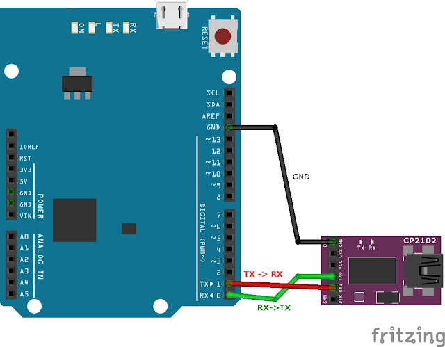
To connect to UART, a USB to UART converter as such FTDI cable can be used. In my case, I used CP2102 adapter. LPC824 board (schematic) pins are compatible with Arduino, therefore D0 pin (P0_0) is Rx and it can be connected to Tx of CP2102 adapter. Similarly, D1 pin (P0_4) is Tx which should be connected to Rx of CP2102 module. Before erasing using Flash magic, the board needs to be reset while ISP button is pressed.
As an alternative to Flase magic, it is also possible to send the following commands manually from serial port.
| From host or controller | Command | Hexadecimal | Description |
| H | ? | 3F | initiate to sync |
| C | Synchronized | 53 79 6E 63 68 72 6F 6E 69 7A 65 64 0D 0A | reply |
| H | Synchronized | 53 79 6E 63 68 72 6F 6E 69 7A 65 64 0D 0A | ack sync |
| C | OK | 4F 4B 0D 0A | |
| H | 12000 | 31 32 30 30 30 0D 0A | freq 12 MHz |
| C | OK | 4F 4B 0D 0A | |
| H | U 23130 | 55 20 32 33 31 33 30 0D 0A | unlock wr and erase with unlock code 23130 |
| C | 0 | 30 0D 0A | success code |
| H | P 0 31 | 50 20 30 20 33 31 0D 0A | prepare sector 0 to 31 for erase or wr |
| C | 0 | 30 0D 0A | success code |
| H | E 0 31 | 45 20 30 20 33 31 0D 0A | erase sector 0 to 31 |
| C | 0 | 30 0D 0A | success code |
Since LPC824 board appears as a serial port called Mbed serial, it can be used in testing UART example also. For that, 0 ohm resistor at SJ9 jumper needs to be changed to connect pin 2 and 3.


No comments:
Post a Comment
Comments are moderated and don't be surprised if your comment does not appear promptly.