Overview
The plotters vary in type, size, and equipped controllers. They commonly come in A3 paper and A4 paper sizes. In term of mechanism, there are two popular types as described in the following figures.
Figure 1. XY plotter with A3 workspace.
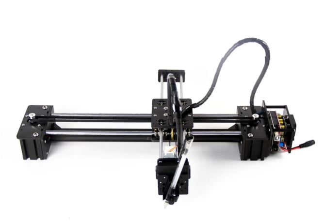
Figure 2. A4 size XY plotter.
They both are CoreXY type drived by two stepper moters to move in XY plane [1]. If the first motor moves A steps and the second motor moves B steps, the movement along X axis is (A+B)/2 steps and the movement along Y axis is (A-B)/2 steps. There are two different type of controllers to choose when ordering a plotter. Plotter with laser support usually come with EBB (EiBotBoard) [2]. If not, it comes with Arduino CNC Shield with A4988 drivers [3].
Assembly Instructions
There is no assembly instruction manual in the parcel when it is delivered. You need to contact to the store and request for the manual by yourself. The following are the instruction manuals for plotter assembly.- Plotter_A3_SDLC9_Assembly_Manual
- Plotter_A3_SDLE10_Assembly_Manual
- Plotter_A4_CDLC7_assembly_manual_Uno
- Plotter_SDLE18_Assembly_Manual
Controller
EiBotBoard
EBB (EiBotBoard) is compact and efficient. It also has a connector to attach laser head. It uses Microchip PIC 18F46J50 microcontroller. The command set for the controller can be found at EBB (EiBotBoard) Command Set [4].
Arduino CNC Shield
Arduino CNC shield can be used with Arduino Uno.
Important Note: There are cloned CNC v4 shields which use Arduino Nano. Those boards are known to have hardware issues and you might need to modify hardware and firmware configuration to make them to work properly.
To control the motion of the stepper motors via Arduino UNO using gcode as input, you can use free software grbl. Grbl runs on Arduino with a 328P microcontroller. You can get source code and use Arduino IDE to compile and load into Arduino Uno. Alternatively, you can download pre-compiled hex file, and burn into Arduino using the following command.
> "C:\Program Files (x86)\Arduino\hardware\tools\avr\bin\avrdude"
-C"C:\Program Files (x86)\Arduino\hardware\tools\avr\etc\avrdude.conf"
  -pm328p -carduino -P\\.\COM3 -D -Uflash:w:grbl_v1.1h.20190825.hex
But this grbl is for standard x, y, and z stepper motors to control 3-axis movements. Our plotters which are depicted above uses CoreXY driving mechanism (also called H mechanism) using combined x and y steps. And instead of z axis motor, it uses a small servo motor to control up and down movement of the attached pen. For that you need to modify config.h file as described below [5].
- In config.h, comment out the following homing lines and enable that of CoreXY.
- 105 // #define HOMING_CYCLE_0 (1<<Z_AXIS)
- 106 // #define HOMING_CYCLE_1 ((1<<X_AXIS)|(1<<Y_AXIS))
- 112 #define HOMING_CYCLE_0 (1<<X_AXIS)
- 113 #define HOMING_CYCLE_1 (1<<Y_AXIS)
- In config.h, to set the homing point as origin, uncomment the following line.
- 129 #define HOMING_FORCE_SET_ORIGIN
- In config.h, most importantly, define as CoreXY plotter.
- 189 #define COREXY
- In cpu_map.h, change PWM frequency 1kHz(for laser) to approximate 50Hz (for servo) as follows.
- 147 // #define SPINDLE_TCCRB_INIT_MASK (1<<CS22)
- 148 #define SPINDLE_TCCRB_INIT_MASK ((1<<CS22) | (1<<CS21) | (1<<CS20)) // 1/1024 prescaler -> 61Hz (for Servo)
- In config.h, disable undesirable PWM power changing by commenting out the following line.
- 587 // #define DISABLE_LASER_DURING_HOLD
I have forked the repository and modified config.h and cup_map.h files. The modified repository can be found at:
After coloning the above repository, we can follow the instructions as described below to load the firmware into Arduino Uno using Arduino IDE [6].
Open Arduino IDE, click 'Sketch -> Include Library -> Add .ZIP Library ...' menu. And open 'grbl' subfolder under the clone folder 'grbl' where you can see 'examples' folder. Then click 'open' button. Arduino IDE will show 'Library add to your libraries'. Open 'File->Examples->grbl->grblUpload' and then compile and upload to Arduino Uno. You can use 'Sketch ->Show Sketch Folder' menu to open the sketch folder. Alternatively, you can got to "grbl\hex" folder which is in the cloned repository and run flash.bat in command windows. Before running the batch file, you can edit it to modify the com port and arduino tools path as necessary.
> flash.bat
Arduino CNC shield can be used with A4988 or DRV8825 stepper motor drivers.

Figure 5. Arduino CNC shield connected with 2 stepper motors, a servo, and XY limit switches.
There are three jumpers namely 'M0, M1, and M2' at each driver socket to set microsteps. When jumpers are left opened, they are LOW because of 100k pull down resistors [8].
| Mode 0 | Mode 1 | Mode 2 | Microstep resolultion |
|---|---|---|---|
| 0 | 0 | 0 | Full step |
| 1 | 0 | 0 | Half step |
| 0 | 1 | 0 | 1/4 step |
| 1 | 1 | 0 | 1/8 step |
| 0 | 0 | 1 | 1/16 step |
| 1 | 0 | 1 | 1/32 step |
| 0 | 1 | 1 | 1/32 step |
| 1 | 1 | 1 | 1/32 step |
On the other hand, the microstep resolution for A4988 stops at 1/16 step.
| Mode 0 | Mode 1 | Mode 2 | Microstep resolultion |
|---|---|---|---|
| 0 | 0 | 0 | Full step |
| 1 | 0 | 0 | Half step |
| 0 | 1 | 0 | 1/4 step |
| 1 | 1 | 0 | 1/8 step |
| 0 | 0 | 1 | 1/16 step |
| 1 | 0 | 1 | 1/16 step |
| 0 | 1 | 1 | 1/16 step |
| 1 | 1 | 1 | 1/16 step |
The rightmost column of black connectors in the above figure are all connected to ground. For limit switch connectors for each axis for connected too. For example, X+ and X- are connected on the PCB. Therefore, it does not matter whether you connect limit switch wire to either one of them. If you put limit switches on the moving head, you can save the number of wires by using only one wire for ground, and single wire for each axis even if one has limit switches at both ends. For limit switchs typical snap action lever arm switches are great. Alternatively, hall effect magnetic sensors can also be used. For that, you need small magnets.
Calibration
When I first used DRV8825 drivers, they did not work. Later, I found out that the potentiometer on the driver needs to be adjusted to drive the motor properly. You can attached a multimeter to the screw driver as illustrated in the following figure and adjust it to get ~ 0.6 V [9].
Figure 6. Arduino CNC shield with DRV8825 stepper motor drivers which is beging adjusted for proper current limiting.
Current limit for DRV8825 is described in the following equation. $$ I_{lim} = \frac{V_r}{5 . R_s} $$ Since Rs is 0.1 ohm for the DRV8825 module, the limiting current can be described as $$ I_{lim} = 2 \times {V_r} $$ For A4988, the limiting current is $$ I_{lim} = \frac{V_r}{8 . R_s} $$ The value of Rs is 0.068 ohm for A4988 module, and the current limit can be expressed as $$ I_{lim} = 1.84 \times {V_r} $$ You also need to adjust parameters for grbl firmware to control the motion correctly. For that you can use serian monitor in Arduino IDE or a serial port utility such as Hercules SETUP utility. After connecting the board to the computer, you can find the com port in device manager. Once you connect the com port using baud rate 115200, 8N1, you should receive a message as follow.
Grbl 1.1h ['$' for help]
[MSG:'$H'|'$X' to unlock]
If you see "[MSG:'$H'|'$X' to unlock]", can run homing by entering '$H' (provided that limit switches are fastened) or just unlock by entering '$X'. If you key in $ followed by enter, help information will be replied.
[HLP:$$ $# $G $I $N $x=val $Nx=line $J=line $SLP $C $X $H ~ ! ? ctrl-x]
Then check your current settings by entering $$. My grbl settings for step/mm, rate, and accel for a driver with 1/16 microstep is as follows.
$100=100.000 (x, step/mm)
$101=100.000 (y, step/mm)
$102=100.000 (z, step/mm)
$110=8000.000 (x max rate, mm/min)
$111=8000.000 (y max rate, mm/min)
$112=8000.000 (z max rate, mm/min)
$120=4000.000 (x accel, mm/sec^2)
$121=4000.000 (y accel, mm/sec^2)
$122=4000.000 (z accel, mm/sec^2)
$130=310.000 (x max travel, mm)
$131=210.000 (y max travel, mm)
$132=100.000 (z max travel, mm)
Depending on your hardware setup, you might need to adjust the parameters to fit your plotter. For that, you can send a gcode command to move a particular distance for example 100 mm in each axis, measure and then adjust step/mm for that axis (e.g. $100). When you first power on the device, it is at (0,0). You can check the status by sending '?' character. And to set it to mm scale, send 'G21'. Thereafter, to move 100 mm along X-axis, you can send the following command.
G00X100.0000Y0.0000
To move at a particular feed rate, use G01.
G01X50.0000Y100.0000F400.0000
After measuring the actual movement with a ruler, you can change and save the corresponding grbl setting, for example, x steps/mm, as shown below.
$100=200.000
To push down the pen, you can use spindle control 'M03' command where speed parameter S used as power. As the maximum is 1000, to turn down the servo, use 10% which is 100 out of 1000.
M03S100
Normal spindle stop command is 'M05'. In our case, turn the servo up which is 5% and then stop.
M03S50
M05
Drawing
Instead of sending gcode manually, you can use Universal Gcode Sender to interface with grbl controller. It is availabe to download at the following link.After opening the software and connecting to the com port, you can run setup wizard by clicking "Machine->Setup Wizard" menu. Setup wizard allows you to calibrate, to enable hard limit, soft limit, and homing to be set easily. To try drawing, you can open a gcode file from "File->Open" menu. It will show the path in the visualizer. You can also edit the gcode by clicking "File->Edit Gcode File" menu. To test drawing with the plotter, you can load the following gcode file and click send button.

Figure 7. Using UGS to open and draw a gcode file.
To generate gcode file from an inkscape drawing, you can install the plug-in from the following link [7].
To install, you can open inkscape, then open 'Edit -> Preferences -> menu'. On the pop up window, check 'System -> System Info -> User extensions' field. In my case, it is at 'C:\Users\aye\AppData\Roaming\inkscape\extensions'. Extract the plug-in files there and restart inkscape. Thereafter, you can see the tool at 'Extensions -> Generate Laser Gcode -> J Tech Photonics Laser Tool ...' menu. General procedure is to draw a svg image in inkscape, select them and convert it to path by clicking 'Path -> Object to Path' menu. Then use the plug-in tool to convert to gcode.

Figure 8. Generating a gcode file.
For our case, we use 10% PWM to push down the pen attached to the servo, that is why we use laser power 100 to generate M03 S100. Although spindle stop command is 'M05', we want to use M03 S50 to move up the servo. Therefore, we put M03 for Laser Off command too. After generating gcode file, we can open it with a text editor, and search and replace all 'M03 S0' with 'M03 S50'.
References
[1] Ilan E. Moyer. CoreXY. 2012.url: http://corexy.com/theory.html.
[2] Brian Schmalz. EBB (EiBotBoard).
url: http://www.schmalzhaus.com/EBB/.
[3] ZYLtech. Arduino Compatible CNC Shield Instructions.
url: https://www.zyltech.com/arduino-cnc-shield-instructions/.
[4] Eggbot. EBB (EiBotBoard) Command Set.
url: http://evil-mad.github.io/EggBot/ebb.html.
[5] Henryarnold. Drawing Robot - Arduino Uno + CNC Shield + GRBL. 2017 May 28
url: https://www.thingiverse.com/thing:2349232.
[6] Grbl. Compiling Grbl. 2020 Dec 03
url: https://github.com/gnea/grbl/wiki/Compiling-Grbl.
[7] J Tech Photonics, Inc. Inkscape Laser Plug-In. 2020 Dec 03
url: https://jtechphotonics.com/?page_id=2012.
[8] Pololu. DRV8825 Stepper Motor Driver Carrier, High Current. 2021
url: https://www.pololu.com/product/2133.
[9] Pololu. A4988 Stepper Motor Driver Carrier. 2021
url: https://www.pololu.com/product/1182.
No comments:
Post a Comment
Comments are moderated and don't be surprised if your comment does not appear promptly.